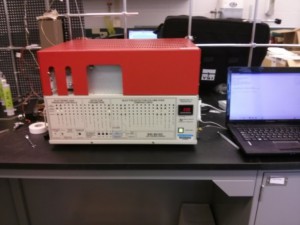
We restored the Gas Chromatograph (GC) after a year long hiatus. The GC took a while to warm up, but thankfully it started running after a few days. Here’s a picture of the GC that we used.
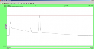
After the GC warmed up, we wanted to find the location of the SF6 and CF3SF5 peaks. First we found the location of the SF6 peak. We set the Electron Capture Detector (ECD) to a temperature of 300C and the Column Oven to a temperature of 50C. Then we injected a standard gas with 150 ppbv of SF6 into the system. We found the peak to occur after approximately 1.20 minutes. (You can see that the baseline is still a little unstable after days of the GC warming up).
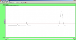
Next we found the location of the CF3SF5 peak. We kept the ECD and Column Oven temperatures constant and then injected a standard gas of 7.7 ppbv of CF3SF5 into the system. We found the peak location to occur after approximately 3.10 minutes.
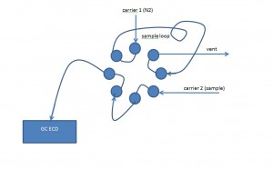
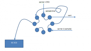
Lastly, we equipped the system with an 8-port valco valve. We rigged the system to load a sample loop with a controlled amount of standard gas. Once the valve was loaded, we could rotate the valve to inject the controlled volume into the GC. Here is a diagram of the system in the load and inject positions:
